department of Mechanical engineering
student development ACTIVitiES
Various number of student development activities are constantly being practiced in each classrooms, enforced by our Center of Learning and Teaching.
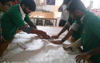
Problem-Based Learning

role play
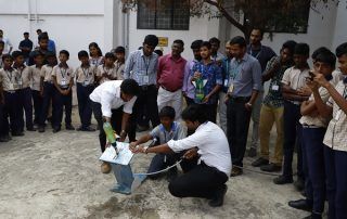
Activity Based Learning
Project-Based Learning
ICT Enabled Classroom

Management Games
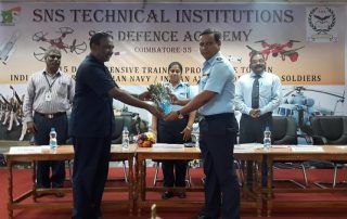
defence training
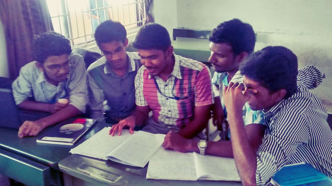
Peer Group Learning

EG MODEL
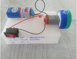
PUMP MODEL
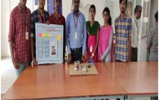
FILTERATION UNIT MODEL
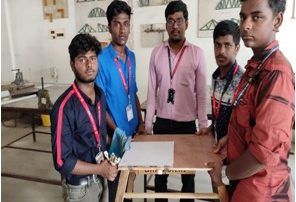
Smart table
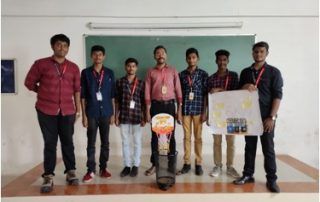
Trash can
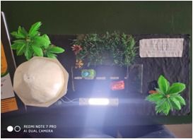
solar energy bulb
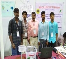
Automatic fish food for dispenser for fisheries

Coupling Mechanism
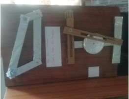
Crank and slider mechanism
Wheel chair cum stretcher
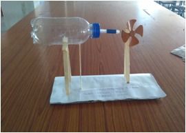
Steam nozzle
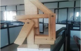
.Governor Mechanism
industrial
case study
Naturally, students are more inductive than deductive, they learn better from examples than from logic. So, we believe that the use of case studies is a very effective classroom technique. Students will be provided with an industrial case study linked with the concept or subject, where they got to explore how their learning are applied in the real world situations. This helps the students to actively engage in figuring out the principles from the examples.
- B. Ashok Kumar, Prof./Mech;Case study on “The application of acoustic emission for detecting incipient of a 60 kW centrifugal pump”;Pump Industries;Pumps are used in most of our domestic and industrial applications. From the data collected from the cavitation is a serious problem encountered in hydraulic pumps. It is essential to detect the incipient of cavitation to avoid it. Once the incipient of cavitation is found, by changing the rotational speed of the centrifugal pump or flow rate, formation of cavitation can be avoided. Detecting the incipient of the cavitation is a very big challenge. This case study “Acoustic emission (AE) technique has been applied for detecting cavitation occurred in the centrifugal pump. A series of performance Tests and NPSH tests were conducted on a two stage ‘David Brown’ 60 kW centrifugal pump (Model DB22) with a maximum capacity of 204 m3/h at an efficiency of 70.6%. Acoustic emission sensors were located at various points. Observations of AE r.m.s. activity during the performance test are displayed. During the performance test, AE activity from the sensor located in the vicinity of impeller on pump casing was found to have the largest magnitude among the magnitude of AE received from other sensors which were fixed on other points as mentioned earlier. Hence, the sensor fixed in the impeller eye position is the best position for correlating AE activity to predict the pump performance. It was observed that the minimum AE r.m.s. value was obtained for a flow rate of 94.5 m3/h. At this flow rate the AE activity generated from the fluid flow within the pump and pipes was lowest in comparison to other flow rates. Either side of this flow rate resulted in increasing AE r.m.s. activity with increased flow rates. Based on these observations it was concluded that the best efficiency point (BEP) must occur where there was minimal flow turbulence in the system, and hence minimum AE activity. A total of three NPSH tests were undertaken at flow rates of 101, 141 and 180 m3/h, As with the performance tests, the best AE signature response was located on the pump casing in the vicinity of the impeller eye and other sides also. At a flow rate of 101 m3/h an increase of 165% in AE r.m.s. levels was observed from an NPSH value of 8.2 to 7 m. Relatively constant levels continued until an NPSH of 5.8 m. then a rapid decrease in AE r.m.s. levels was noticed. With further reductions in NPSH, spikes in AE r.m.s. signal response were observed as the 3% drop in head was reached. Same pattern of AE levels was noticed from the sensors fixed in the suction and discharge flanges. The results from acoustic emission analysis have shown a clear relationship between AE activity measured from the pump casing, suction and discharge pipes, and incipient cavitation. At a relatively high NPSH value, when incipient cavitation is known to occur, an increase in AE r.m.s. levels was observed. However, as cavitation developed there is a reduction in AE r.m.s. levels due to attenuation of AE. Hence, it is suggested that the AE technique is more suitable to detect incipient of cavitation.
- “Dr. B. Ashok Kumar, Prof./ Mech; Analysing hydro abrasive erosion in Kaplan turbine; Chilla hydroelectric plant ;In this case study Erosion of turbine components are addressed. Erosion is one of the serious problem encountered in hydraulic turbines. Sediment flow through hydro turbine causes erosion of hydraulic components resulting in drop of turbine efficiency. Particularly in hydropower plants of the Himalayan region. The sediment flow causes reduction in the active life of reservoirs, increase the erosion of hydro-mechanical equipment and civil engineering structures in the plant. The following methods are currently used to overcome sediment erosion related failures:Removal of sediments, Development of erosion resistant alloys, Coatings of the components, and Optimization of hydraulic design of the components.The measurement of erosion and monitoring of sediment flow in turbine are major concerns in erosion study. The hydro abrasive erosion due to sediment laden water is a complex process and depends on many factors such as sediment characteristics, flow characteristics and properties of substrate materials that is hardness, surface morphology, properties of the coating on the turbine blades and hub. Erosion measurements in prototype plants are difficult due to large sized and non-flat components. An ultrasonic thickness measurement device operating on resonance principle was used to measure the thickness of turbine components before and after repair. In order to create reference points for the measurements all the six turbine blades of a unit were divided into grid cells drawn with paint before repair and then, the remaining grid lines after repair were connected to get the initial grid lines. In the present study, a run-of-river hydropower plant, scheme Chilla hydropower plant in foothills of Himalaya is considered for erosion study. The objective of this case study is to present a simple approach to measure the erosion on the turbine blades, the runner chamber and the draft tube cone of a prototype Kaplan turbine unit. During maintenance of turbine, an ultrasonic thickness measurement device operating on resonance principle was used to measure the thickness of turbine components before and after repair. A total of 4 readings of thickness were recorded in each 25 grid cells on pressure side surface of a blade, both before and after repair. The thickness measurements were performed on 6 turbine blades with 100 measuring points on each. The numbers of thickness measurement inside a grid cell were averaged to obtain a single value of erosion depth inside a grid cell. The erosion depth of a blade was obtained by averaging erosion depth of grid cells in two zones–trailing side and tip side. Cell A1 was the most severely affected due to erosion. The past experience revealed that the cell A1 was even removed due to erosion and cracking. It is found that the maximum and minimum values of erosion depth in different parts of runner chamber. It is clear that the most severely affected parts of the runner chamber were the upper cone and middle cone, whereas the MS cone was least affected. As MS cone zone has diverging shape, it less prone to erosion. The convergent shape and proximity to turbine blades turbulence increased the erosion of middle cone. Other three zones, i.e., upper cone, lower cone and compensating cone were cylindrical in shape. The erosion in the upper cone was higher due to turbulence created by the nearby turbine blades. The measured sediment concentration values throughout the year revealed that a maximum concentration of 3.6 g/l and 5.3 g/l passed through turbine blades in 2007 and 2009 respectively. It was found that 47% of the sediment load passed through only 20 days in 2007 in the hydropower plant. The corresponding values in 2009 were even higher, i.e., 49.2% of the sediment load in just 12 days. The other major finding is that the runner chamber portion near the turbine blade is susceptible to erosion, hence erosion resistant material must be used for this region. The results suggested that high erosion producing sediment concentration have passed through within a few days of the year. The operation of plant can be adjusted during these days to reduce erosion.”
- B. Ashok Kumar, Prof./Mech;Case study on “Detection of Cavitation Phenomena in Reciprocating Pumps using a High-Speed Camera”;Pump Industries;The very fast generation and collapsing of vapor bubbles are not visible to the naked eye. Therefore, the detection of cavitation phenomena has to be performed optically by a high-speed camera. Additionally, the pump was equipped with several pressure sensors to obtain detailed knowledge of the pressure evolution. The experimental investigation of the occurring cavitation phenomena was performed using a horizontal single-acting plunger pump. To observe the generation and the back formation of cavitation in the working chamber and at the suction side valve, the pump was equipped with several pressure-resistant inspection windows. Because of the inspection windows, it is possible to capture the cavitation phenomena with a high-speed camera with a frame rate of up to 100,000 frames per second. Basically, the cavitation types are categorized into three cavitation conditions: incipient cavitation, partial cavitation and full cavitation. Incipient Cavitation: At the beginning of the suction stroke, the working chamber time plot exceeds the vapor pressure for a very short time. This form is called incipient cavitation. The reason for this is the under pressure spike during the opening of the suction side valve. Generally, it can be said that the bubbles in the working chamber are strictly caused by volume expansion. Partial cavitation: If you lower the suction side pressure or increase the plunger speed, you proceed from the condition of incipient cavitation to the condition of partial cavitation. After the under pressure spike during the opening of the valve, the pressure in the working chamber remains nearly constant at the level of the vapor pressure. Therefore, cavitation bubbles will be generated at the beginning of the suction stroke and collapse due to certain pressure conditions. The volume of the vapor cavities of advanced cavitation is increased in comparison to incipient cavitation. Partial cavitation is characterized by complete bubble degeneration at the latest end of the suction stroke. Full Cavitation: When the vapor cavities are degenerated at the beginning of the discharge stroke, this condition is called full cavitation. Very high pressure surges have to be expected and, additionally, a loss of efficiency has to be suspected. Thus, this cavitation condition has to be avoided. A study has been made on the detection of cavitation phenomena in a reciprocating positive displacement pump A high-speed camera was used to capture the occurring cavitation phenomena such as the very fast generation and collapse of cavities. cavitation in reciprocating positive displacement pumps seems harmless and unable to generate damages at the suction valve and in the working chamber. This led to the opinion that cavitation up to certain level is not harmful
- P. Divyakumar, AP/Mech;Case study on Ambassador car; This case is based on ‘product re-launch strategy’ under Strategic Management. Various strategies are discussed in this case which will make us aware in brief about the various business strategies. Management students will clear many of their concepts and will enhance their knowledge about various business strategies currently used in the industry for business growth as well as to re-enter the market. Management faculties can also use this case while discussing various strategies in their class. This case is based on the decision of the HM management when it decided to relaunch the Ambassador car. It highlight the reasons which compelled the company to take this decision, and it also talks about the views of market analyst’s that making cosmetic changes the company will not be able to make any mark in this stiff competitive scenario. The case also talks about the strengths and weaknesses of company and the brand.
- “Mr. P. Divyakumar, AP/Mech;Case study on Demand vs Supply; All markets have a supply and a demand side, leading to an equilibrium price and quantity. The supply and demand of products is a key concept in economics. Briefly, the law of supply and demand states that the availability of a product (supply) and its desire (demand) has a direct effect on the price. Accordingly, if the supply is low and demand is high, prices are high and vice versa. This law is true for most products in the market which can be applied in most market-relevant case interviews. In a perfect market, demand and supply co-incide at a zero-profit price. A perfect market has the following characteristics:
- All goods of a kind are equal (e.g., commodities).
- No transaction costs exist (e.g., taxes, cost to negotiate a contract and to change a supplier).
- Many competitors exist.
- Everyone has the same information.
- For each of the two market participants, consumer and a producer, it is assumed that:
- The lower the price for a product, the more consumers can afford it and want to buy it.
- The lower the price for a product, the fewer producers want to sell it, as the profits are lower.
- Mr. P. Divyakumar, AP/Mech; Case study on Demand vs Supply; All markets have a supply and a demand side, leading to an equilibrium price and quantity. The supply and demand of products is a key concept in economics. Briefly, the law of supply and demand states that the availability of a product (supply) and its desire (demand) has a direct effect on the price. Accordingly, if the supply is low and demand is high, prices are high and vice versa. This law is true for most products in the market which can be applied in most market-relevant case interviews. In a perfect market, demand and supply co-incidence at a zero-profit price. A perfect market has the following characteristics of a kind are equal (e.g., commodities).No transaction costs exist (e.g., taxes, cost to negotiate a contract and to change a supplier).Many competitors exist Everyone has the same information. For each of the two market participants, consumer and a producer, it is assumed that the lower the price for a product, the more consumers can afford it and want to buy it. The lower the price for a product, the fewer producers want to sell it, as the profits are lower.
- “Mr. P. Divyakumar, AP/Mech;Case study on Fiat currency vs cryptocurrency; A Cryptocurrency (or crypto currency) is a digital asset designed to work as a medium of exchange using cryptography to secure the transactions and to control the creation of additional units of the currency. Both a cryptocurrency and an electronic payment system Satoshi Nakamoto in 2008 First decentralised payment network System is peer-to-peer 21 million bitcoins Completely Open source 1BTC = $1258.48 Cryptocurrency is an impressive technical achievement, but it remains a monetary experiment. Even if cryptocurrencies survive, they may not fully displace fiat currencies. As I have tried to show in this presentation, they provide an interesting new perspective from which to view economic questions surrounding currency governance, the characteristics of money, the political economy of financial intermediaries, and the nature of currency competition.
- “Mr. P. Divyakumar, AP/Mech;Case study on Concurrent vs Sequential Engineering; Traditional engineering, also known as sequential engineering. It is the process of Marketing, Engineering design, Manufacturing Testing and Production where each stage of the development process is carried out separately, and the next stage cannot start until the previous stage is finished. Advantages of sequential engineering Easy to track progress and understand the requirements of the project and processes It is well defined for each team member or department.Simple to understand and avoids misinterpretation It is an imposed discipline approach which takes away any misunderstanding Limitations of sequential engineering Increased product cycle time.Change requests from others in the latter stages are often very expensive and difficult to manage Without staged feedback. Final unit cost not economically viable. Concurrent engineering, also known as simultaneous engineering, is a method of designing and developing products, in which the different stages run simultaneously, rather than consecutively. It decreases Product development time, Time to market, Improved productivity, Reduced costs.
- “Dr. V. Gopalakrishnan, AP/Mech; Cryogenic Rocket Engine; Forbes India; Cryogenic Rocket Engine is a simple engine based on laws of Cryogenic science & Newton’s 3rd law of motion. Cryogenic Technology ensures the stability of fuel & by following Newtons 3rd law the trust is generated. These two principles work hand in hand to make this engine a mega success of 20th& 21st Century. Also while comparing Rocket engine with jet engine , thrust produced in rocket engine is outwards and that in the jet engine is inwards. Hence this efficiency cannot be achieved by any other engine.
- Dr. V. Gopalakrishnan, AP/Mech;A Study on Foundry Sand; Shiv Minerals;In the No-Bake foundry process, sand is blended with a small amount of expensive ingredients including a chemical binder and catalyst in a high speed mixer. The ingredients begin a chemical reaction process of hardening when discharged from the mixer to the mold or core box. An important step in this process is to maintain consistent temperature of the sand before it is blended with the ingredients. If the sand is too hot or too cold the amount of ingredients added has to be adjusted, which can create inconsistencies in the castings quality as well as wasting expensive raw material
- “Dr. P.Madhu, AsP/Mech; Making a renewable energy future a reality: Case study; NextEra Energy Partners;Fossil fuel combustion is the major source of greenhouse gas (OHG) emissions, largely in the form of carbon dioxide (CO~), accounting for 85 percent of current net anthropogenic CO2 emissions. Over the past 50 years, fossil fuel consumption has increased fivefold, from approximately 57 exajoules in 1937 to around 282 exajoules in 1988. Predominant among these fuels is the use of coal and oil, though natural gas use is projected to increase rapidly over the next few decades. If fossil fuel consumption continues to grow, a doubling of pre-industrial CO2 concentrations could occur as early as 2030, leading to a projected increase in the global average equilibrium temperature of 1.5 to 4.5°C. In the past three years, a major international study under the auspices of the Inter-governmental Panel on Climate Change (IPCC) has largely confirmed the previous findings of a range of scientific assessments that a continuation of current fossil fuel and deforestation trends will likely increase global temperatures to unprecedented levels. The IPCC calculated that it would take a reduction in global CO2 emissions by 60 per cent to stabilise atmospheric concentrations.
- P.Madhu, AsP/Mech;Renewable energy in the developing world- A Case study;Renewable technologies with exception to traditional biomass are often termed ‘modern renewables’. These include hydropower, solar, wind, geothermal and modern biofuel production (including modern forms of waste-to-biomass conversion). The change & mix of modern renewable consumption over the last 50 years is shown in the chart below. This is measured in terawatt-hours per year and can be viewed across a range of countries and regions. Globally, the world produced approximately 5.9 TWh of modern renewable energy in 2016. This represents a 5 to 6-fold increase since the 1960s. Here we see that hydropower remains the dominant form of modern renewables consumption, accounting for almost 70 percent. Despite absolute growth in production, hydropower’s share is, however, declining as other renewable technologies grow.
- P.Madhu, AsP/Mech;Analysis of a Heat Engine: Case study; Ford Motors Ltd; A heat engine typically uses energy provided in the form of heat to do work and then exhausts the heat which cannot be used to do work. Thermodynamics is the study of the relationships between heat and work. The first law and second law of thermodynamics constrain the operation of a heat engine. The first law is the application of conservation of energy to the system, and the second sets limits on the possible efficiency of the machine and determines the direction of energy flow.Heat engines such as automobile engines operate in a cyclic manner, adding energy in the form of heat in one part of the cycle and using that energy to do useful work in another part of the cycle.A heat engine typically uses energy provided in the form of heat to do work and then exhausts the heat which cannot be used to do work. Thermodynamics is the study of the relationships between heat and work. The first law and second law of thermodynamics constrain the operation of a heat engine. The first law is the application of conservation of energy to the system, and the second sets limits on the possible efficiency of the machine and determines the direction of energy flow.
- P.Madhu, AsP/Mech;Analysis of a Heat Engine: Case study; Ford Motors Ltd; A heat engine typically uses energy provided in the form of heat to do work and then exhausts the heat which cannot be used to do work. Thermodynamics is the study of the relationships between heat and work. The first law and second law of thermodynamics constrain the operation of a heat engine. The first law is the application of conservation of energy to the system, and the second sets limits on the possible efficiency of the machine and determines the direction of energy flow.Heat engines such as automobile engines operate in a cyclic manner, adding energy in the form of heat in one part of the cycle and using that energy to do useful work in another part of the cycle.A heat engine typically uses energy provided in the form of heat to do work and then exhausts the heat which cannot be used to do work. Thermodynamics is the study of the relationships between heat and work. The first law and second law of thermodynamics constrain the operation of a heat engine. The first law is the application of conservation of energy to the system, and the second sets limits on the possible efficiency of the machine and determines the direction of energy flow.
- P.Madhu, AsP/Mech;Residential heat pump- A Case study ; Daikin Heat Pumps; A heat pump is a device that uses a small amount of energy to move heat from one location to another.The working fluid, in its gaseous state, is pressurized and circulated through the system by a compressor. On the discharge side of the compressor, the now hot and highly pressurized vapor is cooled in a heat exchanger, called a condenser, until it condenses into a high pressure, moderate temperature liquid. The condensed refrigerant then passes through a pressure-lowering device also called a metering device. This may be an expansion valve, capillary tube, or possibly a work-extracting device such as a turbine. The low-pressure liquid refrigerant then enters another heat exchanger, the evaporator, in which the fluid absorbs heat and boils. The refrigerant then returns to the compressor and the cycle is repeated
- Sowmya, ASP/MECH;Logistics;Allcargo Logistics Ltd, part of the Avvashya Group, is a logistics firm headquartered in India. Its services comprise global multimodal transport operations (non-vessel-operating common carrier, less than container load, and full container load), pan India container freight stations, inland container depots, third-party logistics, warehousing, contract logistics and logistics parks. The company operates across more than 160 countries through more than 300 offices. In keeping with the growing demand for logistics parks and Grade-A warehouses, Allcargo Logistics has ventured into this segment to offer state-of-the-art warehousing and industrial real-estate solutions. With a number of strategically located logistics parks across India, all in varied stages of development, Allcargo is expanding its nationwide warehousing footprint and tapping into key industrial and consumption centres. Characterised by innovative engineering, quality infrastructure and amenities, compliance with stringent health and safety standards, the warehouses ensure high operational efficiency and enable customers to minimise logistics overheads. An optimised supply chain is essential to business success across sectors. Whether you need end-to-end supply chain management, or a customised solution to optimise your existing supply chain, just leave it to our team of experts. With our robust infrastructure, we help drive your business with a scalable supply chain that matches seasonal demands. Our expertise spans diverse domains like warehouse logistics for automotive, chemical, pharmaceutical, food, e-commerce and fashion and retail.
- Sowmya, ASP/MECH;Logistics Costs; M/S MODERN GARMENTS, MUMBAI; (Mumbai Uni Nov 2003)M/s Modern Garments is the manufacturer of ladies and gents garments, such as tops, shirts, undergarments, etc. Their manufacturing technology is advanced and, at the same time, there are several players who have access to such latest technologies. The supply chain for M/s Modern Garments includes significant purchases of raw materials, stitching of garments, packaging of finished products and supply of goods to its customers. The logistics functions are the key competitive elements in the market. M/s Modern Garments is considering to take over the control over its inbound and outbound logistics functions. These have a direct bearing upon the inventories, reduction in the losses due to transit delays and improvement in transit time and service reliability. However, the company has to look into the cost implications of such changes. M/s Modern Garments have been the leader in the readymade shirts market in India for a number of years. After liberalization, they entered into a joint venture with a French company to expand its business in the area of trousers and T-shirts. Despite the new joint venture, M/s Modern Garments still continues to manufacture its shirts at Thane near Mumbai and has started a new state-of-art garment manufacturing plant at Pune in Maharashtra, to compete with other market players. The company has planned to undertake the distribution of garments made and packed in its plants at Navi Mumbai and Kalyan so as to retain the control over the design, quality and service channel of its products.
- Sowmya, ASP/MECH;Marketing; SUPER DOLLS COMPANY, MUMBAI;Super Dolls is a toy manufacturing company which is in the business for the past two decades. The manufacturing unit is situated in Mumbai, while its sales and marketing are spread over a large geographical area, especially in the major cities across the country. Over the years, a number of competitors have sprung in the field. Far from child’s play, the company found that the toys’ sector is a tough business. Some of the problems faced by it are: There is a massive sale during the festival seasons. If the company’s product is delayed, the valuable market is missed. “Fashion” or “cult” status products influence the market. Any wrong decision in this matter, means loss of sales and build-up of unwanted inventory There are high marketing and promotional costs. If these programmes go out, the sales drop massively Any misjudge of the market can also mean closing down of the company The company has problems regarding stock holding at its distribution centers. This is mainly due to wrong inputs from feedbacks and improper surveys. The company relies mainly on hired fleet of road transport. The services are not up to the mark in terms of delivery schedules, safety of goods from pilferage/theft, and mishandling of product. Marketing strategies are far from adequate. They are not effective enough to counter the strategies adopted by the competitors. You are called upon by the management of Super Dolls to head their logistics operations.
- Sowmya, ASP/MECH;Supply Chain Monitoring;FORD INDIA; Supply chain monitoring ford parts supply & logistics case study. roger merkle former manager, north american inventory planning department. voice of the customer high service levels managed inventories managed safety stock managed costs expediting, overtime voice of the customer (high inventories) (high safety stock) (high costs)expediting, overtime distribution (process-focused) stable fixed costs low inventory stable part mix stable schedules low transportation cost distribution high customer service stable fixed costs low inventory stable part mix stable schedules low transportation cost purchasing low purchase price (high inventory) (stable schedules) (long lead times) purchasing low purchase price low inventory flexible schedules short lead times supply reliable suppliers low inventories short lead times flexible transportation supply reliable suppliers (high inventories) (long lead times) flexible transportation sell returns deliver source (make) return. Analytical Data updated weekly, at best High levels of processing time variability + Forecast error over supply chain process = High safety stock levels Different cultures, processes and practices at each node Material expedited by teams of people at headquarters Highly Reactive – focus on backorders and blame assessment Increasing complex supply chain including external partners and sources as well as non traditional channels Metrics not aligned – Data not common Little ability to prioritize which actions are critical to the business requirements, Voluminous reports – both paper and electronic, Labor-intensive to collect Forecast accuracy and safety stock management
- Sowmya, ASP/MECH;Lean Structure; Donald Cross Corporate; The process industry in Europe employs 6,8 million workers and yields more than €1.6 billion of total turnover, thus accounting for around 20% of workforce and income in the EU region. Being in the center of most industrial processes and having to deal with the strict Page 9 of 75 guidelines of Horizon 2020, regarding energy consumption and efficiency, while still under the rigid economic circumstances of the decade crisis, process industries need to approach a more sustainable mode of operation, reducing energy consumption and emissions while preserving high quality delivered. Managing Warehouses, Compliance, Lean Culture, New Global Logistics.ORG/ Local ,Sales & Operation Planning (S&OP), Process Harmonization To Improve Cost Efficiency, Delayering of Supply Chain 3-1, Consolidate Supplier Base & Transport Costs, Indirect Spend Optimization Project Start up With PMO, Measuring & Develop metrics to optimize logistics, Indirect, optimization projects with stakeholders/ Group Management – Americas logistics team “No I in team”,Compliance & Data transparency (create visibility creates control), Total Customer, Service Solutions/ Service Levels/ Frontline, Develop Warehousing KPI’s/ Benchmark, Transport spend report Air, Ocean, Domestic (Air Freight Spend), 3PL/ Freight Partners, QBR/Budget/ Service, Multiple Supplier Consolidation, Creating a Culture for Change Lean Management is focusing on the organization of all resources in a supply chain by eliminating non value-adding activities (waste) in order to achieve the optimal profitability.
- Sowmya, ASP/MECH;Integrated supply chain strategy;THE CASE OF SPANISH FAST FASHION RETAILER INDITEX-ZARA;The successful implementation of an integrated supply chain strategy enhances total control over the operations and thus enhances speed and flexibility. The objective of this study is two-fold: first to identify the constituents that mold the fast fashion retailing business model, and second to discuss how global leader of fast fashion retailing Inditex-Zara’s product offering is strongly supported by integration of various supply chain operations. The findings suggest that vertical integration through ownership of various operational stages including product design and development, production operation, logistics and distribution channel; appropriate sourcing strategy to meet product needs; application of process/product modularity practices in product design, material procurement and manufacturing to ensure manufacturing flexibility; flexible logistics capability; and all of these seamlessly integrated and coordinated by a centralized IT infrastructure can significantly raise overall supply chain flexibility and responsiveness. Inditex-Zara’s super-responsive supply chain reduces ‘bullwhip effect’, order-to-delivery lead time to stores, ensures lean inventory and high level of responsiveness to adapt and deliver products to stores with latest fashion trends and customer feedbacks at a rapid speed. Thus Inditex-Zara is able to successfully counter the negative effects of short product life cycles, high product variety, demand uncertainty and thus able to closely match product supply to the stores with market demand. This contributes to lower inventory backlogs; avoid mark-down losses and/or inventory stock out.
- Sowmya, ASP/MECH;Thermal Power plant; Koodankulam nuclear power station;As a developing nation we need energy to support our future industrial & domestic needs. But the way to generate this energy does not depend solely on nuclear energy. Throughout the world many developed countries are shutting down their nuclear reactors and starts looking into alternative ways to produce energy in a safer and greener way. India can achieve its future needs but it will not be the safe for the country’s internal security and safety. Koodankulam is a place in the Tirunelveli district in Tamil Nadu, India. It is situated 25 km north-east of Kanyakumari and 35 km from Nagercoil.The place is notable as the construction site of the Kudankulam Nuclear Power Plant. It is also the location of hundreds of windmills used for power generation, eight of which are located inside the grounds of the nuclear plant. Since the beginning of 2011, this place has been embroiled in a nuclear plant controversy over its safety by its people. Recently there have been several struggles by local people against the project. Local people are afraid that in case of a natural disaster the reactor may blast. This paper will deal about the various dimensions of Koodankulam Nuclear Power Plant with both its positive & negative sides.
- Sowmya, ASP/MECH;Differentiating supply chain strategies; This article reports on an investigation of supply chain strategies that are employed by light vehicle manufacturers in South Africa. The research method used was an exploratory and descriptive study. A face-to-face, semi-structured interview questionnaire was administered to senior supply chain practitioners, based on purposive sampling and the data was analyzed descriptively using SPSS software. The findings of the study revealed that both lean and agile supply chain strategies are employed by the manufacturers. All the light vehicle manufacturers followed a lean strategy for their inbound supply chain. While a few of them followed a lean supply chain strategy for their outbound supply chain, others followed an agile supply chain which suggests a leagile supply chain strategy. Three important conclusions can be drawn from the study. Firstly, despite the changing business conditions and increased customer demands, lean supply chain strategy is still the dominant strategy for light vehicle manufacturers in South Africa. Secondly, a supply chain strategy is not all about product characteristics as a determining factor. There are other criteria that could be used to determine supply chain strategies. Finally, light vehicle manufacturers do not always make decisions and implement practices in line with their chosen supply chain strategies. Hence, there are mismatch between practices and strategies. It is recommended that the vehicle manufacturers align their practices with their chosen strategy, since mismatching generally leads to problems and challenges in organizations.
- Sowmya, ASP/MECH;Power Generation; Chandrapura Thermal Power Station; Originally, planners designed Chandrapur TPS to accommodate increasing of power demand and ensure stable power supply in Assam State. The power station was built with one 30 MW generation unit and had been operating since December 1972. At the time of appraisal, Assam was facing a serious power shortage. In view of the region’s inability to meet peak power demand, and in order to gain maximum benefit from valuable oil resources in the state, the Planning Commission of the Government approved this expansion project in July 1979 as a part of the state’s sixth five-year power development plan (1980/81-1984/85). The installation of the additional 30 MW power generation unit at Chandrapur TPS was consistent with development policy as it was then delineated. Due to the recent rapid growth of oil consumption, the Government of India currently is attempting to limit its dependence on oil imports by expanding domestic exploration and reducing domestic oil consumption. India has decided to abolish subsidies for and to deregulate several oil products as well. While the central government’s deregulation policy resulted in the exorbitant escalation of fuel oil prices, the state government has not been able to raise its electricity tariff for political reasons. As a result, Chandrapur TPS has been forced to suspend operations; it can not recover the fuel costs with the low electricity tariff and is no longer financially viable. Assam still faces a serious power shortage, so the project objective remains relevant.
- Sowmya, ASP/MECH;Supply Chain Management: An Integrated Solution; The Textile Industry is characterized by a complex production network which spans many businesses and usually crosses International boundaries. It has become an essential commodity in day to day life like food and water. The verities of production in Textile field has spread in all areas right from apparel to Industrial fabrics, protective Textiles, Composite Textiles, Medical textiles, Automotives, Aerospace and in so many other areas. Now- a -days the product range are not within the periphery of one area but reached at nook and corner all over the world. Today, the sales are highly volatile and seasonal and to fulfill the requirements it needs good capacity planning, production scheduling, process control, inventory management to make the whole thing a profitable proposition. To make an integrated solution which spans stock balancing, inventory management, production planning and distribution scheduling a proper system needs to develop. Hence to make all the systems in order, it is ideal to have a proper supply chain Management in Textile Industries. Flow of information between business partners, producers to distributors and retailers, the inventory optimization, demand – supply is to be perfect through proper supply chain management. ABC Classification: In case of increasing uncertainty in the international market, the customers starts stocking of the materials and hence, subsequent problems arises in logistics and distribution. At that time, it is necessary to see customer profile, his routine demand & accordingly distribution is made. Importances are being empathized on valuable customers for up keeping the customer’s business on line.
- Mr S Hemnath, AP/Mech; Case Study Of The Textile Industry In Tirupur; Bleachers Textile Pvt Ltd The study was carried out in the year 1996. All the data and estimates pertain to the year 1995. Tirupur, chosen as a sample town, represented a typical industry pattern in developing countries with many small and micro enterprises involved in an industrial activity. A lot of attention has been given to the industrial symbiosis model in Kalundborg (Denmark), where a few disparate large units have worked out an effective system to optimize the use of their material and energy resources (as described in Chapter 1). The industrial pattern in Tirupur is very unlike Kalundborg. Tirupur has a large number of small and medium units engaged in similar activities, a pattern much more representative of a developing country.
- Mr S Hemnath, AP/Mech;Case Study on Investigation of fire accident analysis; Sakthivel Cotton mill; Textile industry is main production sector to improve economy of country. It consists of processing units like cotton mill, spinning mill, dyeing units, garments exports. Cotton industry primarily used to convert raw cotton into yarn product. Fire is a main hazard present in all process area of production field. The main causes of fire have many reason that static electricity, overheating, human error, environmental atmosphere and failure of electrical parts in machine. As per statistics date given from National Crime Record Bureau (NCRB), the number of person died due to stumpage is higher than people affected by fire at the time of fire accident. The samples are evaluated with hypothesis and T-Test. The position of fire emergency door is decided based on the result of t-test and evacuation timing calculation.
- Mr S Hemnath, AP/Mech;Case study of Fire Accident in Buildings;The main aim of this study is to find solution to the problem of finding remedial measures to improve the Indian Economy. Even though the Government of India taking several measures to improve the Economy and standard of living of the citizens but still what was achieved so far is well below par. Still today we don’t have any control over Price rise, Inflation, Industrial output, Currency value and so on. So now we have to find some meaningful solution to the above problem that will be useful in discussing the paper
- Mr S Hemnath, AP/Mech;A case study from India on leapfrogging in smart manufacturing; Daimler Pvt Ltd; Globally, manufacturing continues to grow through the decades. It now accounts for approximately 16 percent of global GDP and 14 percent of employment. However, the manufacturing sector’s relative size in an economy varies with its stage of development. In India, Manufacturing accounts for 16% of GDP and has remained relatively stagnant. Manufacturing has also witnessed an onslaught from competitive nations like China, while India suffers from some major technology gaps, and therefore most estimates put India at the level of Industry 2.0 in manufacturing. Germany on the other hand, has maintained its leadership position in Manufacturing and Technology through innovative initiatives like resource efficient manufacturing and Industry 4.0. The Paper seeks to conduct a desk research on the developments on Sustainable Manufacturing processes across the world, and suggest a few critical methods for emerging economies to leapfrog into Industry 4.0., using India as a case study.
- Mr S Hemnath, AP/Mech;Case study on Factors affecting the Indian Economy;The main aim of this study is to find solution to the problem of finding remedial measures to improve the Indian Economy. Even though the Government of India taking several measures to improve the Economy and standard of living of the citizens but still what was achieved so far is well below par. Still today we don’t have any control over Price rise, Inflation, Industrial output, Currency value and so on. So now we have to find some meaningful solution to the above problem that will be useful in discussing the paper
- P.Janagarathinam, AP/Mech;A Case Study of Just-In-Time System in Service Industry;Waiting in lines are experienced in our daily schedule. Waiting lines or queues cause inconvenience to customers. Just-In-Time (JIT), the dignified process of waste reduction and has been a very popular operational strategy because of its success in the manufacturing and production industry over many years. Various benefits like, improved operational efficiency, waste reduction, and faster response have been widely observed by previous researchers. Services are much like manufacturing. Therefore, successful implementation of JIT is vital to manufacturing as well as service industries. JIT focuses on the process, not on product. Therefore it can be applied to every process within manufacturing or service industry. The main objective of this research is to make use of a case study to present various issues regarding implementation of JIT for a service industry. This case study also shows the benefits of reduction in waiting period by employing JIT. The conclusion of this research indicates that JIT system is successful and operating JIT system leads to many advantages to the case industry.
- P.Janagarathinam, AP/Mech;New Market Creation via Innovation: A Study on Tata Nano; A hybrid methodology comprising of a case study on the 2200 USD (equivalent to INR 1,00,000) car Tata Nano and supported with a quantitative survey on a random sample of prospective Nano customers has been deployed. The qualitative case study helps to understand the macro picture on how innovation helped create new market for the masses. The quantitative survey measures the impact of various attributes of Nano on customer’s intent to purchase. These attributes have been identified through interviews of prospective Nano customers. Factor analysis has been deployed to establish corporate brand equity, aesthetics, and value for money & reliability as main attributes of Nano. Regression analysis is used to find out the influence of these attributes on intent to purchase Nano.
- P.Janagarathinam, AP/Mech;CASE STUDY: REDUCING LABOR COSTS USING INDUSTRIAL ENGINEERING TECHNIQUES;Introduce various industrial engineering techniques and use a case study to show how these techniques are applied in practice.The case study presented is from CompanyA, a bathtub manufacturer.The improvement process began with an audit of the current productivity situation.Then, following a master plan, productivity improvement actions were taken one by one.The result was a 20 percent reduction in cost after a two-year project. Because it is not possible to cover all aspects of the project in this chapter, the focus will be on the activities aimed at the reduction of labor cost.We also explain how the scope of the application of industrial engineering techniques is expanding.
- P.Janagarathinam, AP/Mech; Tata “Nano”: The People’s Car; Nano, India’s first “People’s car,” may soon earn a place in history alongside Ford’s Model T, Volkswagen’s Beetle, and the British Motor Corp.’s Mini, all of which made automotive travel within reach of millions of customers who had previously been locked out of the car market. In January 2008 during India’s main auto show in New Delhi, Tata Motors introduced to the Indian public its ultra-cheap car “Nano” that was expected to retail for as little as the equivalent of $2,500, or about the price of the optional DVD player on the Lexus LX 470 sport utility vehicle. This event had driven unprecedented public attention, since Tata’s new vehicle was projected to revolutionize the auto industry.
- P.Janagarathinam, AP/Mech;FEA Analysis: Roadtest of Cooling Fan; EnginSoft; Evaluation of stress and deformations is part of the design process. A good safety factor on fan-radiator gap along time is the aim to assure no-touch condition. An optimization activity is carried out on the shroud. The internally developed shroud design tool can guide CAD parametric geometries and FEA analyses in the construction of a n-dimensional space of the solutions with optimization algorithms (Sobol+Full factorial). The designer can thus identify the best geometrical parameters set (component thickness, height, quantity etc.) to reduce deformations with minimum possible mass contribution (fig.6). The new reinforced shroud is virtually mounted on CFM model and FEA is relaunched for validation.
- K. Prakash, AP/Mech; Solar Panels Mis-Matched Produces Output of Lowest Value; MAS Solar Systems Private Limited, Coimbatore;Confuse misfortunes are because of the absence of indistinguishable properties in the interconnection of sun oriented cells or modules. Bungle misfortunes are a major issue in PV modules and clusters under certain conditions on the grounds that the yield of the whole PV module under most pessimistic scenario conditions is controlled by the sun oriented cell with the least yield. For instance, when one sun oriented cell is concealed while the rest of the module are not, the force being created by the “great” sunlight based cells can be scattered by the lower execution cell instead of fueling the heap. This thusly can prompt exceptionally limited force dispersal and the resultant nearby warming may make irreversible harm the module. Crisscross misfortunes are because of the absence of indistinguishable properties in the interconnection of sun oriented cells or modules. Confuse misfortunes are a difficult issue in PV modules and exhibits under certain conditions in light of the fact that the yield of the whole PV module under most pessimistic scenario conditions is controlled by the sun powered cell with the least yield. For instance, when one sunlight based cell is concealed while the rest of the module are not, the force being created by the “great” sun based cells can be scattered by the lower execution cell instead of fueling the heap. This thusly can prompt exceptionally limited force scattering and the resultant nearby warming may make irreversible harm the module. The impacts of current bungle and concealing on the force yield of single photovoltaic (PV) modules are all around dissected, yet just hardly any examinations address jumble misfortunes at a PV framework level that additionally limit the yearly vitality yield. The straightforward inquiry, what occurs if PV strings with various quantities of modules are associated in equal, has not yet been talked about in detail. If there should arise an occurrence of strings with inconsistent module check, the framework developer must conclude whether to utilize inverters with numerous most extreme force point (MPP) trackers, module-power streamlining agents, or to abbreviate all strings for adjusting the framework. Our discoveries from this investigation open another alternative. The numerical demonstrating of PV frameworks with strings of various length in corresponding to a few others which have an equivalent module check renders befuddle misfortunes beneath 1% for most framework setups. For setups where one string is one module shorter than the others, the crisscross misfortunes fall underneath 0.5%. In this manner strings with inconsistent length may well associate with a practical single-MPP inverter without causing huge vitality yield misfortunes. In addition, ordinary flimsy film PV modules are less touchy to befuddle than translucent silicon based ones. Diodes can be utilized to at the arrangement of board which can remove the most reduced worth. Accordingly, the yield isn’t dropped as much previously. For instance, a 5 board of 50 Watts wherein one board gets mis-coordinated, the yield before situation of diode is around 25 Watts while in the wake of setting diode the yield will be 40 Watts.
- K. Prakash, AP/Mech; Case study on Separation of the different layers of solar panels;MAS Solar Systems Private Limited, Malumichampatti, Coimbatore; Silicon (Si) is the most usually utilized semiconductor material as it shapes the reason for incorporated circuit (IC) chips. Most sunlight based cells are likewise silicon based. The detachment of the layers are troublesome in modules. Monocrystalline sun powered boards are created from one enormous silicon square and are delivered in silicon wafer designs. The assembling procedure includes cutting individual wafers of silicon that can be appended onto a sunlight based board. … Numerous silicon particles are liquefied and afterward re-combined into the board itself. Silicon is a characteristic semiconductor, handily acquired and effectively altered (doped) to proceed varying in sunlight based boards to change over sun oriented vitality into power. Every single electronic gadget have a semiconductor gadgets inside which are most likely produced using doped silicon. Silicon (Si) is the most regularly utilized semiconductor material as it shapes the reason for coordinated circuit (IC) chips. Most sunlight based cells are additionally silicon based. The detachment of the layers are troublesome in modules. Monocrystalline sun oriented boards are delivered from one enormous silicon square and are created in silicon wafer groups. The assembling procedure includes cutting individual wafers of silicon that can be joined onto a sun powered board. … Numerous silicon particles are liquefied and afterward re-intertwined into the board itself. Silicon is a characteristic semiconductor, effortlessly acquired and handily adjusted (doped) to proceed varying in sunlight based boards to change over sun oriented vitality into power. Every single electronic gadget have a semiconductor gadgets inside which are presumably produced using doped silicon. Be that as it may, silicon cells alone can’t give power to your home. They are matched with a metal packaging and wiring, which permit the sun based cell’s electrons to get away and flexibly helpful force. Silicon arrives in various distinctive cell structures: single cell(monocrystalline), polycrystalline or undefined structures, most normally connected with slender film sunlight based boards. This is a significant issue in the first Generation Solar boards. This can be overwhelmed by utilizing second Generation Solar Panels or by utilizing explicit answers for disintegrate EVA sheets which go about as a glue.
- K. Prakash, AP/Mech;Case study on Solar Panels Absorbtion of light only at energy level of 1EV; MAS Solar Systems Private Limited, Coimbatore;Sun powered boards work by engrossing daylight with photovoltaic cells, creating direct current (DC) vitality and afterward changing over it to usable substituting current (AC) vitality with the assistance of inverter innovation. Around 23 percent of approaching sun powered vitality is caught up in the climate by water fume, residue, and ozone, and 48 percent goes through the air and is consumed by the surface. Accordingly, around 71 percent of the all out approaching sunlight based vitality is consumed by the Earth framework. limsy film sunlight based cells (TFSCs) experience the ill effects of helpless light ingestion because of their little thickness, which constrains the vast majority of their viable applications. Surface plasmons created by plasmonic nanoparticles offer an open door for a minimal effort and versatile technique to optically design TFSCs. Here, a deliberate reproduction study is led to improve the assimilation proficiency of undefined silicon (a-Si) by consolidating twofold sided plasmonic bi-metallic (Al–Cu) nanogratings. The upper pair of the gratings along with an antireflection covering are answerable for limiting the reflection misfortunes and improving the assimilation of low frequency obvious light range in the dynamic layer. The base sets are responsible for expanding the ingestion of long frequency photons in the dynamic layer. Along these lines, a-Si, which is a helpless safeguard in the long frequency area, is currently ready to ingest broadband light from 670–1060 nm with a normal reenacted assimilation pace of over 70%, and improved reproduced photocurrent thickness of 22.30 mA cm−2, separately. Also, recreation results show that the proposed structure uncovers numerous other superb properties, for example, little episode point lack of care, tunability, and momentous basic boundaries resistance. Such a plan idea is very flexible and can be stretched out to different TFSCs. This can be overcome by using variable doping materials which has ability to absorb energy level of their own property. This type is used in 3rd Generation of solar panels
- K. Prakash, AP/Mech;Case study on Life of Organic Solar Cells;MAS Solar Systems Private Limited, Coimbatore; A typical organic solar cell consists of two semiconducting layers made of plastic polymers and other flexible materials. The cell generates electricity by absorbing particles of light, or photons. … The exciton splits, allowing the electron to move independently to a hole created by another absorbed photon. As a general solar industry rule of thumb, solar panels last about 25-30 years. However, this doesn’t mean that they stop producing electricity after 25 years – it just means that energy production has declined by what manufacturers consider to be a significant amount Single layer organic photovoltaic cells are the simplest form. These cells are made by sandwiching a layer of organic electronic materials between two metallic conductors, typically a layer of indium tin oxide (ITO) with high work function and a layer of low work function metal such as Aluminum, Magnesium or Calcium. Traditional crystalline solar cells are typically made of silicon. An organic solar cell uses carbon-based materials and organic electronics instead of silicon as a semiconductor to produce electricity from the sun. Organic solar cells have several important advantages. These include flexibility, low cost in both investment and environmental aspects, and semi-transparency. The active materials are made of carbon-based organic and plastic materials, which make the cells flexible, light and can be integrated with buildings and different structures. They also have a low environmental cost The components used to design solar cells should have high carbon rating to increase its life span
- K. Prakash, AP/Mech;Case study on Low efficiency of Solar Tracking System; MAS Solar Systems Private Limited, Malumichampatti, Coimbatore;Solar energy is one of the primary sources of clean, abundant, and inexhaustible energy that not only provides alternative energy resources but also improves environmental pollution.To get a larger amount of solar energy, the efficiency of photovoltaic systems has to made by using a trackinng systems. Solar trackers offer the greatest value proposition in high latitude locations due to the yearly movements of the sun. Trackers direct solar panels or modules toward the sun. These devices change their orientation throughout the day to follow the sun’s path to maximize energy capture. … Because these trackers follow the sun vertically and horizontally they help obtain maximum solar energy generation g system. A single-axis solar tracking system uses a tilted PV panel mount and one electric motor to move the panel on an approximate trajectory relative to the Sun’s position. The rotation axis can be horizontal, vertical, or oblique To track the sun in two directions that is elevation and azimuth, a dual-axis tracking prototype is used to capture the maximum sun rays by tracking the movement of the sun in four different directions. One axis is azimuth which allows the solar panel to move left and right. This issue can be compensated by using more solar panels along with dual-axis solar panel system
- K. Prakash, AP/Mech;Energy Audit: A Case Study To Reduce Lighting Cost;Intech Plus Private ltd,Coimbatore;A count on lighting is done after proper identification and calculation about the replacement of the light as it should not affect the consumers need. In the Analysis , the energy consumption of tube lights along with ceiling fixture lights, CFLs and LEDs are evaluated and compared. Florescent tubes: The usage of 40 W tube light and ceiling tube fixture each 10X4W consumes the specified energy: Total number of tube lights being 208,total energy consumed by the tube lights is (108X40)*1+ (10X100)*1 = 5.32 kW hour.Assuming 7 working hours a day and 22 working days per month, total energy consumption by the tube lights are 5.32*7*22=819.28 kWh. The cost wise comparison is also done assuming Rs.5.00 per unit. The total amount is 819.28*5.00= Rs.4096.4 per month.CFLs: Replacing the 40W tube lights with 12 watts CFLs , total energy consumed by108+100= 208 CFLs is, 208*12*1 =2.496 kWhour. Assuming7 working hours a day and 22 working days per month, total energy consumed by the CFLs are 2.496*7*22=384.384kWh. The cost wise comparison is also done assuming Rs.5.00 per unit. The total amount is 384.384*5.00 = Rs. 1921.92.10 per month. LEDs: Replacing the 40W tube lights with 5 watts LEDs , total energy consumed by 108+100=208 LEDs are, 208 *5*1=1.04 kW hour. Assuming 7 working hours a day and 22 working days per month, total energy consumed by the LEDs is 1.04*7*22=160.16 KWh. The cost wise comparison is also done assuming Rs.5.00 per unit. The total amount is 160.16*5.00= Rs.800.8 It shows that replacing the conventional tube lights with energy saving CFLs or LEDs reduces the energy consumption drastically. In addition to this the CO2 emission is also reduced when the tube lights are replaced. Replacing a single tube light with a CFL will keep a half-ton of CO2 out of the atmosphere over the life of the bulb . A simple change in system can conserve energy and bring down the utility bill amount to a greater extent. Energy audit in all the sectors with few changes in the existing system can conserve energy, which in turn will reduce the power demands in our country. The government can decide policies to initiate the energy audit which will make a great change in the economical status of India in the global market.
- V.S. Kaushik, AP/Mech;EVOLUTIONS OF HUMAN RESOURCE MANAGEMEN;Human resource management, or HRM, is defined as the process of managing employees in a company/ Organisation and it can involve hiring, firing, training and motivating employees. The purpose of Human Resource Management lies in successful utilization of people to attain specific as well as organizational goals. Human Resource Management typically means to engage, improve and preserve sufficiently capable employees, to implement the activities essential to achieve organizational aims. HRM has to prepare human resource planning, to recruit, select, place, induct, train and develop the human resources, to arrange for performance appraisal and to achieve the organizational objectives like to earn profit, growth and expansion, survival, diversification etc.
- V.S. Kaushik, AP/Mech;HUMAN RESOURCE POLICIES;To improve industrial relations by evolving a suitable machinery for the settlement of disputes. To encourage mutual negotiations. To prepare and execute labour welfare programme. To arrange all possible facilities for the health, education and other welfare programmes. Clear and specific, yet flexible enough to meet the changing conditions Compliance with all appropriate law and regulation. Agreement with one another and reflection of an overall true and fair view approach to all employees Identify the purpose and objectives which the organization wish to attain regarding to its Human Resources department. Analyse the factors under the organization’s HR policy will be operating
- V.S. Kaushik, AP/Mech;FORECASTING IN HRM;Suzi Automation Pvt.Ltd;A statement of what is judged likely to happen in the future, especially in connection with a particular situation, or the expected weather conditions: economic forecasts. A number of organizations, especially public sector units (PSUs) in India are facing the problem of surplus labour. It is the result of surplus labour that the companies later on offer schemes like Voluntary Retirement Scheme (VRS) to eliminate surplus staff. Changes in the business environment like competition, technology, government guidelines, global market, etc. bring changes in the nature of the job. This means changes in the demand of personnel, content of job, qualification and experience needed. HRP helps the organization in adjusting to new changes.
- A. Natarajan, ASP/Mech;Automation in Turning;Swagath Industrial Corporation, Nallampalayam, Coimbatore;Swagath Industrial corporation is in the production of domestic pumps for which the casting items are machined in house. Earlier they were employing conventional lathes for turning the pump components and they were facing low production, high rejections and poor surface finish. When the market demand increased they were not able to meet the demand due to lower production from conventional lathes. Hence they went for CNC Machines for their turning requirements. With the installation of CNC Machines they could increase the production five fold with fewer rejections and very good surface finish. In conventional lathes machining was dependent on the skill of the operator whereas in CNC Lathes, programming takes care of the machining cycle and the operator needs only to load and unload the components from the machine for every cycle.
- A. Natarajan, ASP/Mech; Manaul Molding Vs Automated Molding system; Santhi Casting Works, Narashimanaicken palayam, Coimbatore;Santhi casting works is in the production of automotive castings and they were employing Conventional Jolt Squeeze machines for producing sand molds to make the castings. By this method, productivity was lower, rejections were high and there was no consistency and there was always shortage of skilled moulding operators. When the demand went up they were not able to supply the castings in time and the management decided to install automatic molding machines. After installing the automatic molding machine, the production fo castings went up by 4 times with minimum manpower and with good quality, good consistency and less rejections. The management feels that even though the initial investment is high, they were able to deliver the castings both in volume and in time with less rejection rate and good consistency in quality of the castings.
- A. Natarajan, ASP/Mech;PCB production Manual Vs Automated;Aiswarya Enterprises, Idayarpalayam, Coimbatore; Aiswarya Enterprises is in the process of manufacturing PCS boards and LED lightings. They were employing manual labor for producting the PCB board with lower output, higher component rejections and less consistency in the quality of the PCB Boards. Because of these factors the customers were not happy and when the demand went up the management decided to buy an automated PCB making system. After installing the automated system, the production went up by 8 times with better quality and good consistency. Now they are able to meet the increasing demand as well as they need not depend on the skilled workmen.
- Naveen Kumar, AP/Mech;Chernobyl Disaster: Case study;The Chernobyl disaster was a nuclear disaster which occurred on April 26, 1986 at the Chernobyl Nuclear power plant, Ukraine. At that time, Ukraine was part of the Soviet Union. This accident was rated level 7, the most severe level, on the International Nuclear Event Scale. Large areas of Ukraine, Belarus, and Russia were badly contaminated. About 60% of radioactive fallout landed in Belarus. About 360,000 people needed to be moved to other places, where they could live after the accident. Many people suffered from long term illnesses and some people were even diagnosed with thyroid cancer and acute radiation poisoning. Most of the people affected have not died yet. When and if the people involved die of cancer, or related diseases, it will be hard to tell if this was because of the accident. The report thinks that up to 4,000 people may die from long term diseases related to the accident. Range from 4,000 to 27,000 by the Union of Concerned Scientists or Greenpeace who estimate that between 93,000 – 200,000 people died as a result of the disaster. The other three reactors at Chernobyl continued to operate after the disaster because there were not enough other power plants in Ukraine to meet the energy demands. Reactor 2 was decommissioned in 1991 after a fire in turbine hall. Reactor 1 was decommissioned in 1996, and reactor 3 decommissioned in 2000. In 2018, a 3800 panel, 1 megawatt solar plant was opened next to the former nuclear plant.
- Naveen Kumar, AP/Mech;Three Mile Island: Case study; The Three Mile Island Nuclear Station (TMI) consists of an 840-megawatt (MW) reactor (Unit 1) and a 960-MW reactor (Unit 2) located about 10 miles southeast of Harrisburg, Pennsylvania, on an island in the Susquehanna River. At about 4:00 a.m., March 28, 1979, the main feed-water pumps connected with one of the two Unit 2 steam generators shut down, causing an automatic and almost simultaneous shutdown of the Unit 2 turbine.The accident halted the development of the U.S. Nuclear power industry for 30 years. During that time, no new nuclear power plants were approved. Several that were under construction at the time of the accident were completed. It also relied more heavily on coal and natural gas to power electric generation. That added a lot of greenhouse gases to the atmosphere than nuclear energy would have. As a result, global warming has caused more extreme weather events, rising sea levels, and many climate change effects. The accident at Three Mile Island was caused by a combination of hard-to-handle machinery, poorly trained or incompetent operators, and a regulatory process that lulled management into neglecting its own responsibilities. Congress, the public, the regulators, and the nuclear power industry reacted. Some overreacted, but there were also positive actions. The impact of the accident seemed to have a decay time constant that is, time required for the impact to diminish by half of about two years. This period is probably related to decay time of about one year for congressional and press interest.
- Naveen Kumar, AP/Mech;Bhopal Disaster: Case study;Bhopal is known for its historical records, artificial lakes and greenery but most of all, the city is remembered across the globe for the worst industrial mishap of the world. On December 3, 1984, the world’s worst industrial catastrophe occurred due to the leak of Methyl isocyanate gas from the Union Carbide India Limited company (UCIL) in Bhopal 3 leak of toxic methyl isocyanate gas at a Union Carbide plant in the central Indian city of Bhopal produced history’s worst industrial disaster, stunning India and the world Post-midnight on December 3, 1984, poisonous gas that leaked from the factory of Union Carbide in Madhya Pradesh capital Bhopal killed thousands of people directly. The incident is now known as the Bhopal disaster or Bhopal gas tragedy. As per official records, the Bhopal gas tragedy killed 3,787 people. The figures were updated by the Madhya Pradesh government later as the immediate official estimate had put the death toll due to gas leak from Union Carbide factory at 2,259. However, activists fighting for justice for Bhopal gas tragedy victims put the figures of death between 8,000 and 10,000. In an affidavit, submitted in 2006, the government said that the Bhopal gas leak caused 5,58,125 injuries that included approximately 3,900 severely and permanently disabling injuries.The gas leak in the Union Carbide was reported after midnight on the intervening night of December 2 and 3. The incident had taken place at the Plant Number C of the Union Carbide factory in Bhopal.
- M.K.RAHGUL POOPATHI, AP/Mech;FORD PRODUCTION SYSTEM;FORD;In 1913, Ford introduced assembly line manufacturing, a totally new approach in automobile making. Ford also became the first automobile maker to adopt 3D visualization tools like CAD, CAM in its manufacturing operations in the 1970s. In the mid-1990s, Ford revamped its operations, to induce greater flexibility and enhance the efficiency of its manufacturing processes. The reengineering effort was known as Ford Production System (FPS). 87YHNBU on the famous Toyota Production System, FPS aimed at developing and applying the best practices in automobile manufacturing. FPS involved the implementation of techniques used in lean manufacturing. Apart from using advanced technologies to help reduce waste, FPS emphasized the human aspects as well. It required its employees to form teams called work groups, and empowered managers to take work decisions without wasting time. Ford implemented the FPS in its plants across the world and realized improved productivity levels and financial performance. Ford initially produced cars using the Craft Production System (CPS). Under CPS, all cars were produced with same basic chassis and engine but with different designs according to individual customer preferences and tastes. However, in CPS, the manufacturing costs were high and did not decline with greater volumes. By 2003, all the plants of Ford had adopted FPS in their operations. It was estimated that after the implementation of FPS, Ford had achieved savings to the tune of $500 mn per year. The personnel at the plants also received web-based training while best practices were identified and shared between the plants. By mid-2003, Ford was in the process of standardizing manufacturing operations across all its plants globally.
- M.K.RAHGUL POOPATHI, AP/Mech;JUST IN TIME PRODUCTION;TOYOTA;JIT originated in Japan. Its introduction as a recognised technique/philosophy/way of working is generally associated with the Toyota motor company, JIT being initially known as the “Toyota Production System”. Within Toyota Taiichi Ohno is most commonly credited as the father/originator of this way of working. The beginnings of this production system are rooted in the historical situation that Toyota faced. After the Second World War the president of Toyota said “Catch up with America in three years, otherwise the automobile industry of Japan will not survive”. At that time one American car worker produced approximately nine times as much as a Japanese car worker. Taiichi Ohno examined the American industry and found that American manufacturers made great use of economic order quantities – the traditional idea that it is best to make a “lot” or “batch” of an item (such as a particular model of car or a particular component) before switching to a new item. They also made use of economic order quantities in terms of ordering and stocking the many parts needed to assemble a car. Ohno felt that such methods would not work in Japan – total domestic demand was low and the domestic marketplace demanded production of small quantities of many different models. Accordingly Ohno devised a new system of production based on the elimination of waste. In his system waste was eliminated by: just-in-time – items only move through the production system as and when they are needed; autonomation – (spelt correctly in case you have never met the word before) – automating the production system so as to include inspection – human attention only being needed when a defect is automatically detected whereupon the system will stop and not proceed until the problem has been solved. In this system inventory (stock) is regarded as an unnecessary waste as too is having to deal with defects. Ohno regarded waste as a general term including time and resources as well as materials. He identified a number of sources of waste that he felt should be eliminated: overproduction – waste from producing more than is needed; time spent waiting – waste such as that associated with a worker being idle whilst waiting for another worker to pass him an item he needs (e.g. such as may occur in a sequential line production process); transportation/movement – waste such as that associated with transporting/moving items around a factory; processing time – waste such as that associated with spending more time than is necessary processing an item on a machine; inventory – waste associated with keeping stocks; defects – waste associated with defective items. At the time car prices in the USA were typically set using selling price = cost plus profit mark-up. However in Japan low demand meant that manufacturers faced price resistance, so if the selling price is fixed how can one increase the profit mark-up? Obviously by reducing costs and hence a large focus of the system that Toyota implemented was to do with cost reduction.
- M.K.RAHGUL POOPATHI, AP/Mech; DISASTER MANAGEMENT;The flood that devastated Kerala in August 2018, following unprecedented heavy monsoon rain, was among the five major extreme flooding events in the world between 2015 and 2019, the hottest five-year period on record, according to the World Meteorological Organisation (WMO). The report, titled “The Global Climate in 2015-2019” and released on the eve of the United Nations Climate Action Summit in New York, provides an assessment of the state of the earth under the increasing influence of climate change and its impact. It says that the global average temperature has increased by 1.1°C since the pre-industrial period, and by 0.2°C compared to 2011-2015. Although data from the last six months of 2019 were not included, the report said that this year, too, would most likely join the preceding four years to be “the warmest of any equivalent period on record globally”. The flood in Kerala in August 2018 was the fifth biggest in the world during the five years from 2015, after similar events in China (June-July 2016), North-eastern India (August 2017), Sierra Leone (August 2017) and Japan (June-July 2018). There is increasing evidence that human-induced climate change is responsible for the rise in extreme weather events all over the world. The report estimates that over 20,000 people died in extreme weather events during 2015-2019 and in all, such events resulted in $572 billion in economic losses worldwide. Around 30 per cent of the world’s population now live in climatic conditions that deliver potentially deadly temperatures at least 20 days a year. Among all weather-related hazards, tropical cyclones were associated with the largest economic losses, with floods, landslides and associated loss and damage. The hazard with the maximum economic loss was Hurricane Harvey in 2017, which led to an estimated economic loss of more than $125 billion. The period from 2015 to 2019 also saw a continued rise in carbon dioxide levels and other greenhouse gases in the atmosphere which set new records. Carbon dioxide growth rates were nearly 20 per cent higher than the previous five years. Carbon dioxide stays in the atmosphere and the oceans for centuries, and will continue to cause a rise in temperature, in turn leading to the melting of ice, the retreat of glaciers, rise in sea level, ocean temperatures and extreme weather events. Rising carbon dioxide concentrations have also led to an increase in ocean acidification. At the same time, the level of oxygen has been on the decline in the open and coastal oceans, including estuaries and semi-enclosed seas, the report points out. The capacity of the oceans to absorb heat is a critical part of the climate system, and the report indicates that ocean heat content has reached record levels since 2015. The year 2018 had registered the largest ocean heat content values on record, with 2017 ranking second and 2015 third. The WMO report says the likelihood of many of such extreme weather events has been significantly increased by anthropogenic climate change, and evidence is mounting that it is the medium and low-income countries and the poor of the world who are more exposed and vulnerable to such climate variability and extremes.
- M.K.RAHGUL POOPATHI, AP/Mech;UTILITARIAN THEORY;There is a difference between rule and act utilitarianism. The act utilitarian considers only the results or consequences of the single act while the rule utilitarian considers the consequences that result of following a rule of conduct . Why the two approaches? Consider the following case: Someone goes to the doctor. The person is ill, experiences pain and dysfunction. The doctor performs a series of test and examinations. The person returns to the doctor’s office to learn of the results, the diagnosis and prognosis. The doctor is aware that the tests all show that the person has a disease that is incurable and life threatening. In fact even under the most aggressive treatment option there is a survival rate of less than 15% for two years. The doctor is considering what would be GOOD to tell the person. Should the person know the truth or should the person be told something other than the truth? Which is better? Which is the right thing to do? What would be GOOD to do? The act utilitarian might calculate that in telling the truth there will be a great deal of pain and hardly any pleasure at all The person will be upset, their family will be upset, the doctor will be upset in informing the ill person that there is nothing that the doctor can do to alter their condition. The doctor’s staff will be upset seeing the person come in for whatever treatment there may be. On the other hand if the doctor makes up a story concerning the diagnosis and prognosis that is not true but that gives the ill person more time to enjoy life before the illness makes it obvious that the end is near, well then the results are different. The doctor is not so upset in seeing the person, the doctor’s staff is not upset. The family and friends of the person have some more time with that person to enjoy things instead of being morose and depressed. So the ACT utilitarian might calculate that the GOOD is to lie. The rule utilitarian would need to consider what would the long term consequences be if doctors were to lie to those who come to them and have life threatening, incurable illnesses. The rule utilitarian might calculate that people would no longer be able to trust their doctors and this would break down the confidence they need for their therapies to be effective. The RULE utilitarian might calculate that there is far more harm in lying and so the GOOD is to tell the truth. The same result might obtain were there to be a consideration of cheating on an examination. The single act might produce a great deal of happiness for the cheater, teacher, family and friends. The rule of cheating might produce quite the opposite result as society could no longer trust that the doctors, lawyers, engineers, repair people etc.. really know what they are doing and deserve their position. Rule Utilitarianism (RU) has no rule other than UTILITY. Every act is evaluated according to the utility. Does it or doesn’t it produce HAPPINESS. Utilitarians must maximize HAPPINESS. They must never accept unhappiness if they can minimize it . Both ACT and RULE utilitarians must ASSUME NOTHING. They must actually poll or measure what act will produce the greatest utility. The difference is that the ACT UTILITARIAN measures the consequences of a SINGLE ACT. The RULE UTILITARIAN measures the consequences of the act repeated over and over again through time as if it were to be followed as a RULE whenever similar circumstances arise. NOTHING is right or wrong in itself for a utilitarian. NOTHING! It all depends on the consequences of the act, the results are what matters not the act.
- A.VIMALKODEESWARAN, AP/Mech; Boiler Tubes Failure: Case study;National Fertilizers Limited ; When boiler no 3 was running hissing sound was noticed from Northeast side of economizer and leakage in the coils were detected and water was leaking out before E.P. duct. After cooling down the manhole cover of economizer & ISSH were opened and found the leakage in extreme north bottom. the observation are that bottom loop N-S in the segment was found leaking and having 3 mm hole, moreover the coil was totally eroded over 3 meter in length and its thickness was reduced to 2.5 mm. Economizer tube leakage was occurred due to superheater fireside ash erosion and corrosion. Fireside ash corrosion is a function of the ash characteristics of the fuel and boiler design. It usually is associated with coal firing. Ash characteristics are considered in the boiler design when establishing the size, geometry and materials used in the boiler. Combustion gas and metal temperatures in the convection passes are important considerations. There are many reasons due to which the failure of boiler tube occurs some are Caustic Attack, Oxygen Pitting, Hydrogen Damage, Acid Attack, Stress Corrosion Cracking (SCC), Waterside Corrosion Fatigue, Super heater Fireside Ash Corrosion, High temperature Oxidation, Water wall Fireside Corrosion, Fireside Corrosion Fatigue, Short-term Overheat, Long term Overheat, Graphitization, Dissimilar Metal Weld, Erosion and Mechanical Fatigue. There may be some other reasons depends upon the service conditions but we can diagnose the reason in advance by visual inspection and NDT techniques which can save the production loss of the industry and increase the safety of workers
- A.VIMALKODEESWARAN, AP/Mech; Recycling of oleochemical wastewater for boiler feed water using reverse osmosis membranes – Case study ;Wastewater recycling appears to be attractive for water conservation. THE oleochemical wastewater treatment using an advanced process that comprises ultrafiltration (UF) and reverse osmosis (RO) membranes. Prior to the membrane process, the oleochemical effluent was first treated using a biological treatment system that was installed by the factory owner. The quantity and quality of the permeate stream of the membrane system were then periodically monitored over 43 days. The results showed that the system functioned effectively in reducing the chemical oxygen demand (COD), hardness content and the amount of total dissolved solids (TDS). However, the system started to deteriorate after 15 days of operation. Membrane biofouling was suspected to have occurred in the RO membrane. Nevertheless, the fouling problem could be resolved by chemically cleaning the RO membrane using a sodium hydroxide (NaOH) solution every 3– 5 days. Despite of the fact that data set for a longer period is needed to provide a more comprehensive study on the biofouling mechanism of membrane.
- G.Tharanitharan, AP/Mech;Failure of Shaft due to Critical Speed of Shaft and Improper pulley placement ; VG Industry;VG Industries is the leading service Sector for Automobile repair and Maintenance. In the Industry having so many Machine available with common single Prime mover. so Lengthy line shaft is attached here to drive all machine. Here Survival of line shaft is too low. Replacing shaft every 8months.Investigated about this problem. identified the proper Solution to overcome this problem. Because of Improper pulley Placement the shaft failed at above critical speed. so we overcome this Situation Pulley is placed at Right place based upon the design calculation and operate the Prime mover within Critical Speed of shaft(Whirling Speed of Shaft).
- G.Tharanitharan, AP/Mech;Failure of Propeller Because of its Higher Length;VG Industry;Some of the Automobile, between Prime movers and Wheel having lengthy Shaft. Because of Heavy Torque and Speed the Lengthy Shaft will fail due to Self Weight of Shaft. Investigated this Problem, here Shaft Subjected to Pure Tensile Strength and Pure Torque. Maximum Stress Contribution in this Situation Shear Stress Compared to Tensile Stress. To overcome this Situation, Instead of Lengthy Shaft we can use two or three Coupling in between for Smooth Driving. but Little Power loss while driving the shaft. we can operate this shaft in all Speed and Torque without any Failure.
- G.Tharanitharan, AP/Mech;Failure of Shaft due to Bending Stress and Torque;VG Industry;In VG Industry, Lengthy Shaft used to drive all Machine with one Common Prime mover. Length of Shaft Approximately 1m.Four Pulley are Mounted on Shaft. Two Pulley A,B at Extreme left and Right Corner .Another Pulley C is Fitted 300mm Away from right of Left Side Pulley. Pulley D is also attached 400mm to Left of Right Side Pulley.Bearing X and Y Attached to the 100mm away from left and Right Side bearing respectively. Diameter of Shaft is approximately 30mm.Shaft Failed in one Condition .Investigated this problem with Same practical Setup. Because of bending Stress the shaft will fail. Based on Design Calculation we found the Maximum Bending Stress at pulley C .We designed Shaft based on Maximum bending Moment (Pulley C).Replaced 30mm Pulley diameter to 50mm.Now Smooth Running of Shaft without any Deflection and Failure.
students'
mini projects

Design and fabrication of pantographic mechanism
Sed ut perspiciatis unde omnis iste natus error sit voluptatem accusantium doloremque laudantium, totam rem aperiam, eaque ipsa quae ab illo inventore veritatis et quasi.

Pneumatic can crusher machine
Sed ut perspiciatis unde omnis iste natus error sit voluptatem accusantium doloremque laudantium, totam rem aperiam, eaque ipsa quae ab illo inventore veritatis et quasi.

Pendulum based power generator

Metal bending operation

Electromagnetic suspension

Fuel level indicator and fuel theft alarm

Tilting device

Thermodynamic Refridgerator

Beam engine mechanism

Automatic handbrake release system

Slider crank mechanism

Pneumatic power hammer

Automation of pump

Scissor lift

Bar feeding machine

Butter making machine

Motorized screw jack

Automatic flame off

Groundnut harvester

Gearless power transmission

Free energy generation

Motorized corn peeler

Manual Plougher - seed sower

Emergency Doorlock

Welding slag remover

Suspension system

Pneumatic rod bending machine

Rotating gate


